Verification and recurrence of ***** vulnerability in the wireless communication system of China Urban Rail Transit
Published:
Introduction
1. This vulnerability currently exists in many subway lines of China, if it was disclosed before CNNVD officially announces it (Once the vulnerability is announced, the subway communication systems will be upgraded and fixed), it has the potential to be used by criminals to further cause severe social harm. Therefore, part of this project is confidential
2. Am I secret-related personnel? No, I am not. In effect, the project is divided into 2 parts and are studied by 2 group of people separately. The goal of the first part(theoretic) is to figure out the specific rationale behind this vulnerability and how it can be exploited by attacks. Obviously, people working on this part are secret-related. They have already finished their work and drew us a conclusion that it can be exploited by the man-in-the-middle(MITM) attack
3. According to the theoretic instruction, another group of people (me and 2 younger students) were summoned to achieve the recurrence and verification of the MITM attack in the subway wireless communication system, which becomes the second part(practical) of the project. To be more specific, we have to build an LTE experimental platform to actually conduct the MITM to prove that this attack indeed can be implemented in the system
- Notice that we only implement basic MITM attack without further exploiting this vulnerability
Notice
Since this project was finished, quite a lot of the trial and error processes I recorded earlier in this article have been deleted, leaving only the last feasible solution
- For example, as for the LTE networking devices. At first, we even used a real 4G base station. Later, we chose an elementary (cheap) kind of Software Defined Radio(SDR) equipment called “LimeSDR”. Finally, we adopted the more professional USRP equipment
Environment and Tools
| Category | Specification | Number |
|---|---|---|
| IDE | Clion2022 | |
| LTE Stack | srsRAN 21.04 | |
| SDR | Ettus USRP b200mini | x4 |
| PC | Desktop Laptop | x1 x2 |
| OS | Ubuntu18.04 | x3 |
| Antenna | xN | |
| Metallic Enclosure | Iron box Aluminum box | x2 x2 |
Design
Overview
1. Thanks to researchers from German for publishing the paper “Breaking LTE on layer two” which provides us with lots of instructions on MITM or named in the paper as “aLTEr” attack against LTE. However, their instructions only stay at the theoretical level, which means that we still need to do a lot of groping work for the actual implementation of this attack
2. A normal LTE communication is like:

What we have to do is to insert the pseudo base station into the normal communication link and tamper with a piece of data:

3. The problems and difficulties are:
- In LTE protocol, data will be encrypted or decrypted once enter the PDCP layer, but the pseudo base station does not have the valid key to do that
- Some channel parameters change in real time, which makes it difficult for the pseudo base station to maintain a stable connection
Malicious Relay Establishment
1. A normal LTE uplink communication process is shown below: (The function of each layer please refer to here)

2. To cope with the first problem mentioned above, we could only relay data under the PDCP layer (at the RLC layer) by socket:
- As the PDCP layer of our pseudo station doesn’t have the right key to decrypt data, we cannot let the data continually going upper but relay the ciphertext directly

3. To realize the relay, or in other words, to establish the LTE connection, we have to go through the following steps:
- In fact, there is a process called PLMN selection (including cell search) before them. But this part has no relation with our research, so we skip it here

4. There are 3 transmission modes of RLC layer: Transparent Mode (TM), Acknowledged Mode (AM) and Unacknowledged Mode (UM). The “TM” and “AM” mode are used to transmit data for the connection establishment; “UM” mode is later used to transmit the user data, so it doesn’t appear in the pic above
- step 1-6: RRC connection (1-2 in TM mode)
- Generally, these steps are used to establish the initial connection between normal devices and our pseudo devices, we don’t need to modify them
- Many tests have proved that RRC connection can be completed directly by pseudo equipment without forwarding the reply of normal equipment. So, to realize the relay connection, we only need to relay all data in subsequent steps
- step 7-16: Attach & RRC connection reconfiguration (All in AM mode)
- 7: Attach request and PDN connectivity request (PDN connectivity request aims to establish the “default bearer” between UE and P-GW)
- 8-9: Authentication (Confirm the identity between UE and MME and establish the EPS security context)
- 10-13: Security mode (This process will enable the EPS security context to activate the communication between UE and MME through the confirmed code)
- 14-16: When 14 arrives, UE and MME will establish the EMM-CONNECTED status, then MME will send UE an “activate default/dedicated bearer context request”, and UE will reply a corresponding “accept” to establish the “EPS bearer”
- To be honest, we don’t need to know every step very well while relaying them, just locate “AM” mode in the source code and forward all the data come through
User Data Tampering
1. The rationale behind user data tampering is already illustrated in detail in the Breaking LTE on layer two. In short, although there is confidentiality protection(encryption) in LTE, we could still tamper with data in cyphertext form, since LTE in specific version lacks the integrity protection

Development
Experimental Platform
1. The conceptual structure of the platform is shown below:
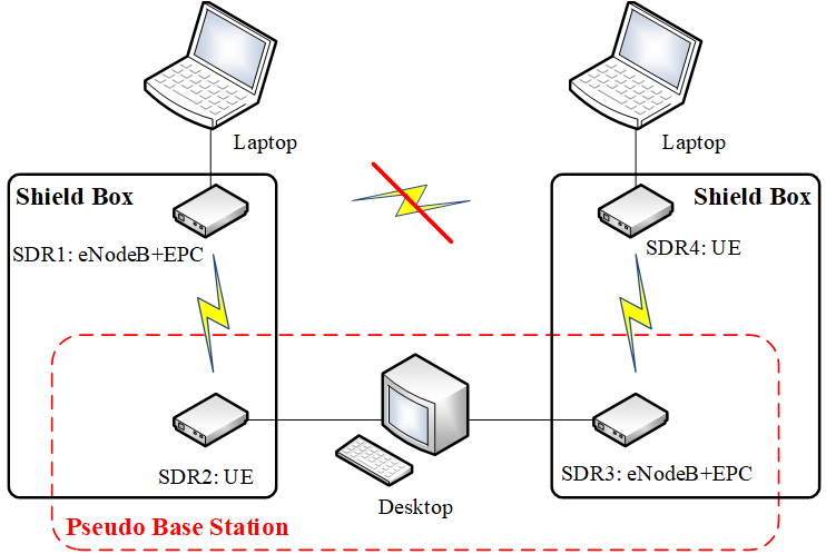
2. The physical establishment of the platform is shown below:
- In the middle are actually 2 displayer screens we’ve connected to the single desktop

Hardware
1. SDR-USRP B200mini: We could deploy LTE stack on such device to simulate the UE and eNodeB+EPC separately. (Base station and core network should be deployed on a single SDR) It can be easily connected to a computer by its self-contained USB cable

2. Shield box: During our early experiments, we found that the connection between 2 SDR device would be frequently disturbed by the wireless signal of the national communication carriers. Thus, we decide to craft 2 shield boxes to isolate our device from the public network


Software
1. OS: All 3 computers are installed with Ubuntu 18.04 operating system
2. USRP Hardware Driver(UHD): Install the environment on each PC to drive USRP device
- Dependence:
sudo apt-get install libboost-all-dev libusb-1.0-0-dev doxygen python3-docutils python3-mako python3-numpy python3-requests python3-ruamel.yaml python3-setuptools cmake build-essential
- Installation:
cd /home
mkdir workarea-uhd
cd workarea-uhd/
git clone https://github.com/EttusResearch/uhd
cd uhd
git tag -l                               //Get the full list of the published versions
git checkout v3.15.0.0                   //Choose a specific version (3.15_LTS)

cd host
mkdir build
cd build
cmake ../
make

sudo make install
sudo ldconfig
export LD_LIBRARY_PATH=/usr/local/lib    //Update the environment variable
- UHD FPGA image file:
sudo uhd_images_downloader
- Test (without device):

3. srsRAN stack: srsRAN is a 4G/5G (we only focus on 4G part) software radio suite developed in C++. It consists of srsUE (SDR UE application), srsENB (SDR eNodeB application) and srsEPC (Core network implementation with MME, HSS and S/P-GW)
- Dependence:
sudo apt-get install build-essential cmake libfftw3-dev libmbedtls-dev libboost-program-options-dev libconfig++-dev libsctp-dev
Installation: For the further development on source code, we download the source code instead of direct installation. Then edit and build it with IDE “Clion” (After building, the source code will generate the corresponding executable cpp files: srsue/srsenb/srsepc)
Configuration: Generally, there are several fields in the configuration file of each LTE element (ue.conf, enb.conf, epc.conf) need to be customized. However, to save space, such processes are not recorded here
Joint Debugging
1. The template shell command to enable each device is:
sudo PATH_TO_THE_EXECUTABLE_FILE PATH_TO_THE_CONFIGURATION_FILE
For example, if I want to enabel the SDR(UE), the command is:
sudo /home/Desktop/srsRAN1/cmake-build-debug/srsue/src/srsue /Desktop/srsRAN1/srsue/ue.conf
Since eNB should be running together with EPC on another computer, usually I open 2 terminals and execute the following commands separately:
sudo /home/lte/Desktop/srsRAN1/cmake-build-debug/srsepc/src/srsepc /Desktop/conf/epc/epc.conf

sudo /home/lte/Desktop/srsRAN1/cmake-build-debug/srsenb/src/srsenb /Desktop/conf/enb/enb.conf
3. After executing the above commands, you can open a new terminal and input ifconfig. There will be a new network element on each computer: 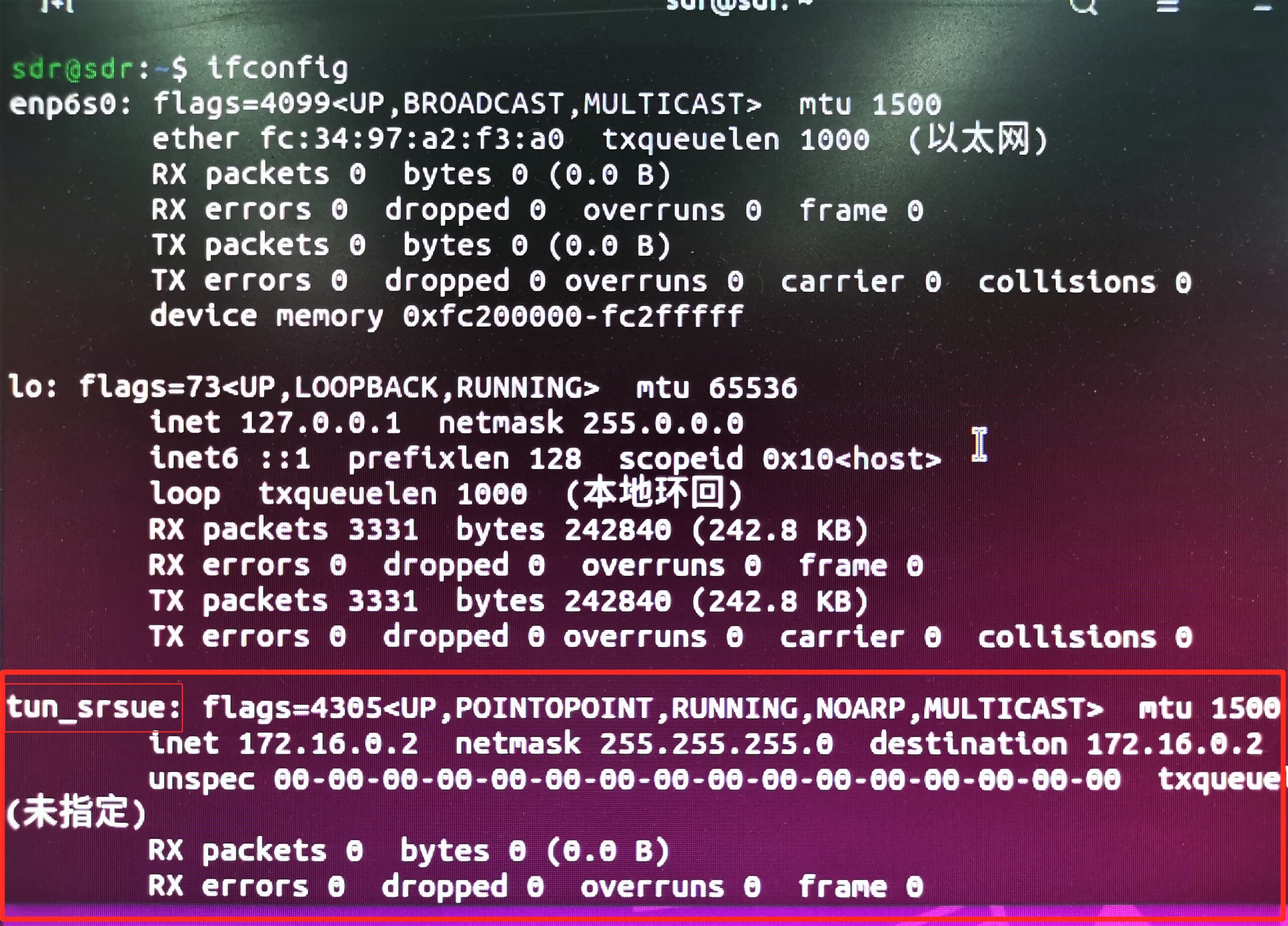
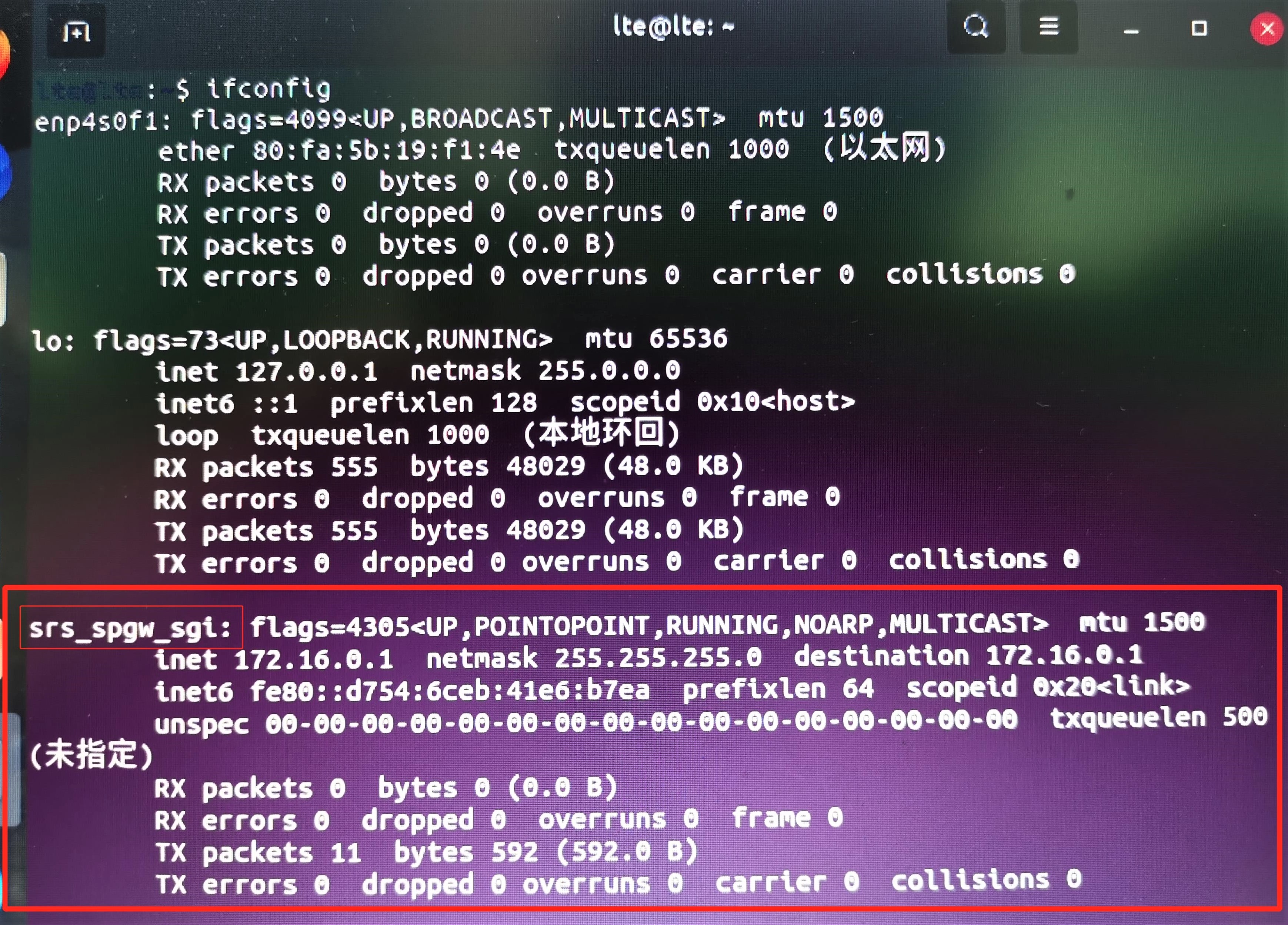
If 2 device were successfully connected, you can ping each other to test the connection. In the pic below, I use PC with SDR(UE) to ping PC with SDR(eNB+EPC):
- Because we’ve write several
printf()functions in the source code, the data flow during thepingis also shown in the right terminal which is enabling UE

4. We also used the “Wireshark” to capture the data flow of SDR(UE). We found the actual interactions basically match the conceptual steps mentioned above (3rd pic in this section):
- step 1-7:

- step 8-16:

Source Code Modification
1. Works above are actually regular setups of an LTE network. To achieve the malicious relay, we have to modify the source code of LTE stacks running on our pseudo-relay device
2. Due to the sensitivity of this project, I cannot show the specific modification process here, but can only briefly describe the steps from a very abstract level:
- AM (Before RRC reconfiguration)
- Find interfaces that belong to “AM mode” between RLC and PDCP in the source code
- Insert Socket functions to relay data that flow through the interface
- AM (After RRC reconfiguration)
- Since the RRC connection is reconfigured, our pseudo device do not know the new parameters to maintain the connection
- Thus, we can only guess the parameters. Specifically, 2 parameters:
- Channel Quality Indication (CQI)
- Scheduling Request (SR)
- Once we got the correct parameters, we could establish the stable connections
- Use Socket functions to relay the remaining data interactions of “AM mode”
- UM (User data transmission)
- Locate the targeted data package in the flow through obvious features such as length
- Conduct manipulation on the cyphertext
Experiment
For security reasons, the experiment process and result are unavailable for now.