Design of LED traffic light brightness-adaptive system based on microcontroller
Published:
Introduction
1. This is actually the enlightenment project of my life, which opened the door of my development career. It is the first time for me to apply the abstract knowledges I learned in class into practical engineering tasks. Although it is relatively elementary to look back on now, it is of great significance to me
2. The LED traffic lights currently used in various working conditions are mostly of constant luminance, while light sources with constant luminance are easy to be interfered by the environment. Therefore, this project aims to design the brightness-adaptive system of LED traffic lights
3. The main idea is to endow the automatic function of brightness adjustment to the LED signal lights through the microcontroller(MCU), so as to achieve the effect of energy conservation on the premise of ensuring traffic safety
Environment and Tools
| Category | Specification | Number |
|---|---|---|
| IDE | Keil uVision5 | |
| Circuit Design | Altium Designer | |
| Microcontroller | STC15W408AS | x1 |
| Electronic Components | LED DuPont line Capacitor … | xN |
| Traffic Light | Green Red Yellow | x1 x1 x1 |
| PC | ThinkPad S5 | x1 |
Design
1. The hardware part consists of five parts: (corresponding to the numbers in schematic diagram below)
- Photosensitive circuit
- Power supply circuit with buck converter
- Microcontroller minimum system
- LED traffic light driving circuit
- Lamp beads check circuit
2. As for the software part, it can be divided into 4 parts:
- Pulse-Width Modulation(PWM)
- Analog to Digital(AD) sampling (collect luminance and current values)
- traffic light control
- Failure detection
3. This design takes STC15 as the controller, and uses the photoresistor to collect the environment luminance for LED brightness adjustment, and uses the built-in AD function of MCU to calculate the value of LED lighting current as the judgment basis (According to Ohm’s law I=U/R, we can directly judge the failure through the voltage obtained by AD sampling)
Development
1. Schematic diagram

2. PCB diagram

3. Source Code
#include <STC15F2K60S2.H>
#include <intrins.h>
#include <stdio.h>
#include <eeprom.h>
#include <stdlib.h>

unsigned char Hour, Minute, Second, Num_50Ms, Eeprom_Data, T[5], T1[5];
unsigned int AD_Val, x, x1, label = 0, Eeprom_Addr, flagr = 1, flagg = 0, flagy = 0, flaggs = 0;
unsigned long p = 0, q = 0, o = 0, r = 0;

void Delay1000ms(){        // @11.0592MHz
    unsigned char i, j, k;
    _nop_();
    _nop_();
    i = 43;
    j = 6;
    k = 203;
    do {
        do {
            while (--k);
        } while (--j);
    } while (--i);
}

void Delay1us() {
    _nop_(); _nop_(); _nop_();
}

void Delay1(unsigned int z) {
    unsigned int x;
    for (x = z; x > 0; x--);
    Delay1us();
}

// UART init
void UartInit(void){        // 9600bps@11.0592MHz
    SCON = 0x50;
    AUXR |= 0x01;
    AUXR |= 0x04;
    T2L = 0xE0;
    T2H = 0xFE;
    AUXR |= 0x10;
}

// Timer init
void Timer0Init(void){      // 50ms@11.0592MHz
    AUXR &= 0x7F;
    TMOD &= 0xF0;
    TL0 = 0x00;
    TH0 = 0x4C;
    TF0 = 0;
    TR0 = 1;                // Start timer 0
    ET0 = 1;                // Start the interrupt of timer 0
    EA = 1;
}

unsigned long AD_sampling(unsigned int in, unsigned int compensate){
    unsigned long out=0, tmp=0;
    unsigned int AD_Cur, m=0;
    while (m != 100) {
        ADC_CONTR = in;
        while ((ADC_CONTR & 0x10) == 0) {}
        AD_Cur = (ADC_RES << 8) + ADC_RESL;
        tmp = AD_Cur + compensate;
        out = out + tmp;
        m++;
    }
    out = out / m;
    return out;
}

void main(void) {
    unsigned int i, j = 0;
    P3M1 = 0x00;
    P3M0 |= 0xc8;             // 1100 1000
    P1M1 |= 0x07;             // 0000 0111
    P1M0 = 0x00;              // 0000 0000
    UartInit();
    TI = 1;
    P1ASF = 0x07;
    CLK_DIV |= 0x20;
    Delay1000ms();
    Delay1000ms();

    /*----------------------AD collect current values----------------------*/
    // Collect normal current values when the system starts for the first time
    q= AD_sampling(0xE8, 0);  // 1000
    o= AD_sampling(0xEA, 0);  // 1010

    //T & T1 represent the normal value of green & red light respectively
    sprintf(T, "%ld", q);
    sprintf(T1, "%ld", o);

    // Store the collected current value into EEPROM
    Eeprom_Addr = 0x0000;
    IapEraseSector(Eeprom_Addr);
    for (i = 0; i < 4; i++) {
        Eeprom_Data = T[i];
        IapProgramByte(Eeprom_Addr, Eeprom_Data);
        Eeprom_Addr++;
    }
    for (i = 0; i < 4; i++) {
        Eeprom_Data = T1[i];
        IapProgramByte(Eeprom_Addr, Eeprom_Data);
        Eeprom_Addr++;
    }
    o = 0;
    q = 0;

    P3 &= 0x37;            // 0011 0111
    Timer0Init();          // Start timer 0
    while (1) {
        /*-----------------------------Fault detection----------------------------*/
        if (label != 0) {
            EA = 0;
            P3 |= ~0x37;   // 0011 0111

            // Collect the current values now
            p= AD_sampling(0xE8, 4);
            r= AD_sampling(0xEA, 7);
            Delay1000ms();

            // Read the current values stored in EEPROM for comparison
            Eeprom_Addr = 0x0000;
            for (j = 0; j < 4; j++) {
                Eeprom_Data = IapReadByte(Eeprom_Addr);
                T[j] = Eeprom_Data;
                Eeprom_Addr++;
            }
            q = atoi(T);
            for (j = 0; j < 4; j++) {
                Eeprom_Data = IapReadByte(Eeprom_Addr);
                T1[j] = Eeprom_Data;
                Eeprom_Addr++;
            }
            o = atoi(T1);

            // If detected values < threshold, turn on the corresponding alerting LED
            if (p < (75 * q) / 100) { P14 = 0; }
            if (r < (75 * o) / 100) { P13 = 0; }

            label = 0;
            EA = 1;
        }

        /*------------AD collect luminance (photosensitive voltage)------------*/
        ADC_CONTR = 0x89;     // 1001
        while ((ADC_CONTR & 0x10) == 0) {}
        AD_Val = (ADC_RES << 8) + ADC_RESL;
        x = 15 * ((AD_Val / 10) + 1);
        x1 = 20 * ((AD_Val / 10) + 1);

        /*--------------------------------PWM-------------------------------*/
        if (flagg){           // control green lamp
            P37 = 0;
            P36 = 0;
            P33 = 1;
            if (x1 <= 100)
                P33 = 1;
            if (x1 >= 2000) {
                P33 = 0;
                Delay1(2000);
                P33 = 1;
                Delay1(350);
            }
            else {
                P33 = 0;
                Delay1(x1);
                P33 = 1;
                Delay1(350);
            }
        }
        if (flagr){           // control red lamp
            P33 = 0;
            P36 = 0;
            if (x <= 75)
                P37 = 1;
            if (x >= 1500) {
                P37 = 0;
                Delay1(1500);
                P37 = 1;
                Delay1(350);
            }
            else {
                P37 = 0;
                Delay1(x);
                P37 = 1;
                Delay1(350);
            }
        }
        if (flagy) {         // control yellow lamp
            P37 = 0;
            P33 = 0;
            P36 = 1;
        }
        else
            P3 &= 0x37;
    }
}

/*-----------------------Traffic light control------------------------*/
void Timer0_Int(void) interrupt 1 {
    Num_50Ms++;
    if (Num_50Ms >= 10){                     // 0.5s?
        if (flaggs)
            flagg = 0;
        if (Num_50Ms >= 20){                 // 1s?
            Num_50Ms = 0;
            Second++;
            if (flaggs)
                flagg = 1;
            if (Second >= 25){               // Set time duration of red to 27s
                flagr = 0;                   // Turn off red, turn on green
                flagg = 1;
                if (Second >= 54) {
                    flaggs = 1;
                    if (Second >= 57) {
                        flaggs = 0;
                        flagg = 0;
                        flagy = 1;
                        if (Second >= 60){   // 60s?
                            flagr = 1;
                            flagy = 0;
                            Second = 0;
                            Minute++;
                            label = 1;       // Start the current value check
                        }
                    }
                }
            }
        }
    }
}
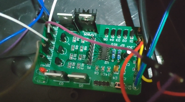
4. Figure
- Connect our circuit board between the power supply of the traffic light and the lamp sets

Experiment
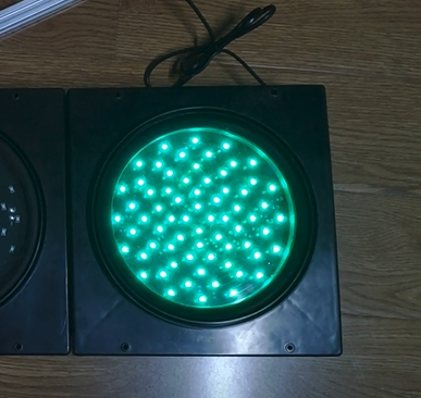
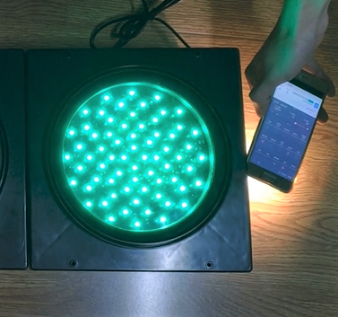
1. Function of brightness-adaptive
- We can see the traffic light become brighter when the environment luminance become higher
2. Function of failure detection
- Normally, both alarm LEDs(left bottom) are unlit
- Then we removed several beads of green lamp through soldering, and the green alarm LED lights up after the periodical failure detection

