Device Configuration
Introduction
As mentioned in the project, I’ve set up a simulation shooting range in my laboratory according to the network topology of high-speed railway signal system, and the topology diagram is shown below. This article roughly records my networking process

Layer 3 Switch
Cisco
1. Device overview
- This device corresponds to the SSDN switch in the figure
- The layer 3 switch is Catalyst 3560G series:

2. Connect for configuration
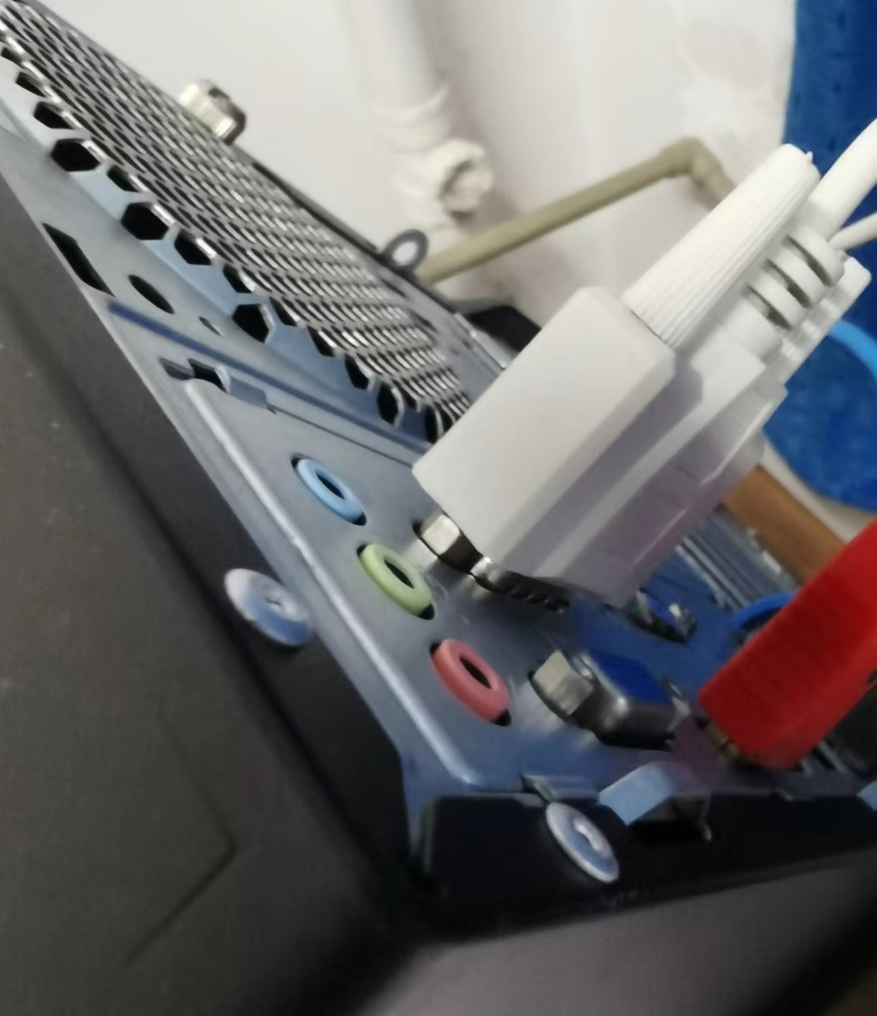
- Usually there is a console interface behind the switch

- Connect it with PC by the console cable
3. Set up for configuration
- Download the Hyper Terminal which provides us with the terminal to configure devices
- Set up a new connection, and select the cluster communication port(COM) which was former connected with console cable

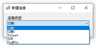
- When you see the
Switch>, it means that you have successfully connected to your device

4. Configure
- Here are some useful commands to configure Cisco switches
enable
conf ter

// Create vlan "xx" and configure IP (address, mask)
vlanxx
int vlan xx
ip add 192.168.4.1 255.255.255.0

// Include ports in vlan xx
int g0/7
switchport mode access
switchport access vlan xx

// Enable routing between vlans
ip routing

// Configure static route (destination address, mask, destination gateway)
ip route 172.110.2.0 255.255.255.0 192.168.2.2

// Save and exit
exit
write

// Show configurations
show vlan
show int vlanxx
show ip route
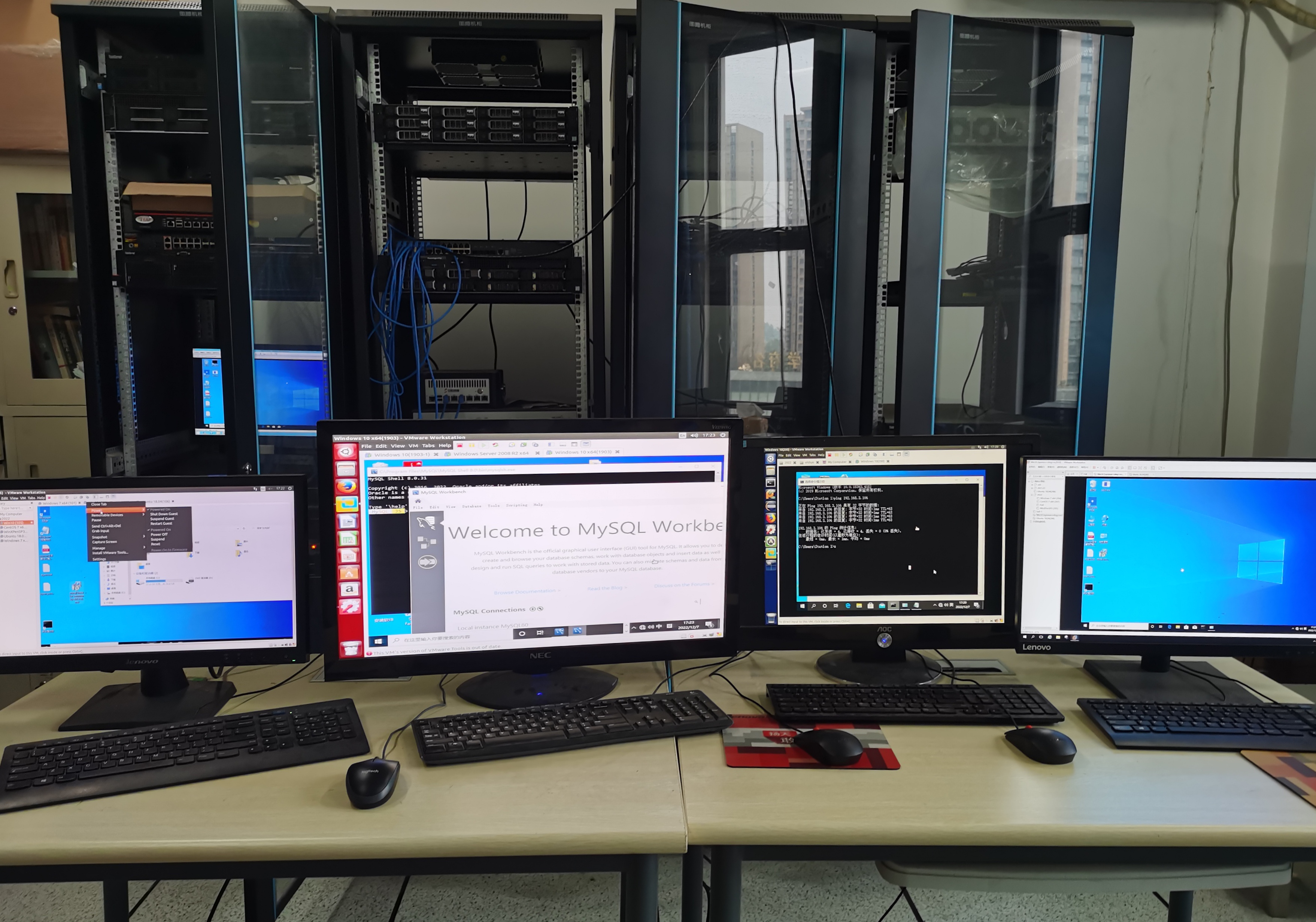
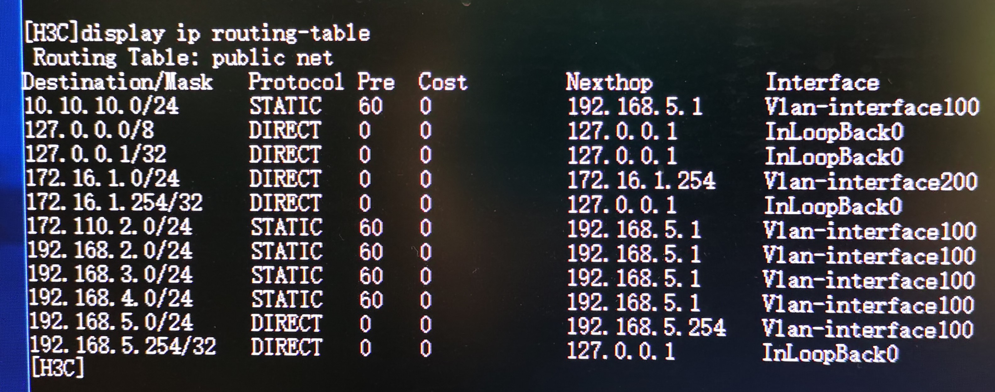
- The final configuration of my range is shown below, it is exactly the same with the topology


- Then I only need to configure the network of every computer and server and connect their network cards to the switch interfaces accordingly
H3C
1. Device overview
- The H3C layer 3 switch in my lab is S3600 series

2. Configure
- Actually I didn’t add this switch in my network in the end, so here I just simply record some commands of its configuration
sys

// Create vlan "xx" and configure IP (address, mask)
vlan xx
int vlan-interfacexx
ip add 192.168.5.254 255.255.255.0

// Include ports in vlan xx
vlan xx
port g1/0/1
port g1/0/2 to g1/0/10

// H3C switches enable routing between vlans by default

// Configure static route (destination address, mask, destination gateway)
ip route-static 192.168.5.0 24 192.168.5.1

// Save and exit
q
save

// Show configurations
display ip routing-table
display vlan
display int vlan xx
Router
UTT
1. Device overview
- This device corresponds to the Router in the figure
- The router is HiPER 840G:

2. Connect for configuration
- Use a PC to connect to its LAN interface, then open the browser and input the IP address of this LAN to login the configuration page (The default IP of my device is 192.168.1.1)
3. Configure
- Usually we focus on the configuration of LAN interfaces(left) and the static route(right)
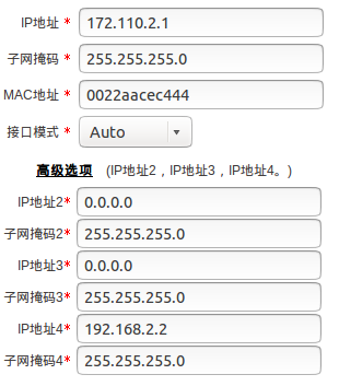

- Notice that if you changed the IP of LAN interface, the address of configuration page will change accordingly. In my case, it has changed to 172.110.2.1
4. Further explanation
- Here I want to emphasize the role of static route. In case you have to connect 2 networks that are not in the same segment, you have to configure the static route of both network bridges
- In my case, network bridges are Cisco Layer 3 switch and UTT router. Devices in network segment 172.110.2.0/24 access devices in segment 192.168.3.0/24, 192.168.4.0/24 and 10.10.10.0/24 via the router’s LAN4 (192.168.2.2), which is in the same network segment with switch’s VLAN40 (192.168.2.1), vice versa